Flashing Turnigy Plush 18A SiLabs ESC with BLHeli Firmware

According to many multirotor flyers, BLHeli firmware for SiLabs based ESCs gives better control, more responsive handling, and better motor control over stock firmware.  This is the process I used to flash the firmware of my Turnigy Plush 18A ESCs.

In case any of my links expire, here is a link to the BLHeli Master Folder

First, you’ll need an SiLabs Toolstick.  I bought mine here: SiLabs Toolstick at Mouser
You’ll need to solder some wires to the toolstick in order to connect it to your ESC.  The connections are covered in this document or see my pictures below.
20130307_192837

20130307_202347  20130307_202310 20130307_20293220130307_203026

Next, find your ESC in this document.  Solder connections at the indicated spots.  I used Servo connectors so that I had an easy connector to the Toolstick.  I used a servo extension cable to solder onto the Toolstick.  This way, the toolstick has a male end and the ESC has a female end.
20130304_225857

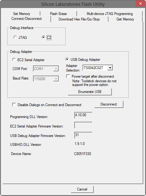
Now that you have connectors on the Toolstick and the ESC, install SiLabs Flash Utility.  Once installed, plug in your toolstick and fire up the Flash Utility.  When open, go to the “Connect/Disconnect” tab and select your USB Debug Adapter.  Power up your ESC and connect the toolstick to it.  Next, click Connect.
2013-03-07_205454

You should see your device detected.  If there is a prompt to update your toolstick, go ahead and click OK.
2013-03-07_205534

Click on the “Download Hex File/Go/Stop” tab and then browse to the hex file for your ESC.  For this, I used Turnigy Plush 18A version 10 Multi.  If this is for a multirotor, use the Multi version.  Check the box for “Erase all Code Space before download”.
2013-03-07_205505

Once the hex file is selected, click on Download.
2013-03-07_205544

Click OK and the flash completes.
2013-03-07_205555

BLHeli is now on your ESC.  Go back to the “Connect/Disconnect” tab and click Disconnect.  Connect the toolstick to the next ESC and repeat the process for each ESC.

Once all your ESCs are programmed, You’ll need to calibrate the throttle.  I use a KK2 board to control my tricopter, so I power up my copter/KK2 and instantly hold button 1 and 4.  The screen will say “throttle passthrough” if successful.  This will pass the throttle to all the output channels so the ESCs will all calibrate to the same throttle.  Put your transmitter to full throttle until the ESCs make a few low to high tones.  When high throttle is set, you’ll hear a few low to high tones, then it will then do a series of double beeps.  Move the throttle to the lowest position.  Once the ESCs beep high to low a few times, the throttle range is calibrated.  Page 4 of this document covers this procedure or see the following picture.
2013-03-08_000250

If you want to adjust any settings manually, you can use BLHeli Setup to adjust settings, save settings, or load settings to your ESCs.

*Note – After flashing my ESCs, all motors spun the wrong way so I had to reverse a couple wires on each motor.  Not sure why this is, and you can reverse the rotation using BLHeli Setup, but swapping the wires was easy enough for me.

So far, I notice that the stability of the tricopter is somewhat improved.  I notice more that the motors are quieter and seem to run smoother.  I’ll have more test data tomorrow once I get it in the air.

The Art of Prop Balancing

If there was one aspect of building a tricopter for video use I thought would be most difficult, removing vibration is not it.  Unfortunately, it is the killer of good video and the most elusive demon to exorcise.  Cheap props make the process more difficult, but who can argue over the price of china-made GWS style props when you’re crashing all the time?  Vibration makes video have “jello”.  Apparently, “jello” is the term people use to describe the wobbly, horizontal lines or generally liquid video you’ll get from too much vibration on your copter frame.  While there are many gimbal designs on the internet to dampen vibration, stopping it at the source is the best solution.

My scenario uses a DT750 brushless outrunner with a 10×4.7 GWS style slow-fly prop.

Step 1: Balance the motor bell housing.  In a previous post, I have links to videos on how to use an iPhone and sound to balance the motor housing.  Use tape on the bell housing to add weight and counteract a heavy portion of the housing.  While these methods use the motor in action to measure vibration and feedback, it is also possible to disassemble the bell housing from the motor and use a prop balancer to find the heavy spots.  This is the long way and what I found is that after balancing using the seismometer iPhone app, the bell housing was almost perfect when I put it on the prop balancer.

Step 2: Balance the prop.  Some people swear they can balance a prop by trial and error.  Those people have a gift.  Get a gift for yourself and buy a prop balancer!!  Seriously, do not make excuses – just buy one.  I bought a DuBro like this and I see others recommending magnetic styles like this. Sand away plastic from the top of the heavy sides of the prop until it rests on the balancer perfectly horizontal.  I use a rough grit until it’s almost perfect and then finish the job with a high grit like 1000 to make the surface smooth again.

Step 3: Dynamically balance.  Mount the prop onto motor, but don’t mount it so tight that you cannot move the prop.  Mount it tight, but not “locked” into place.  While you my have balanced the bell housing and the prop, physics says the combination of the two will inherently have flaws.  The goal here is to find the position of the prop which has the least vibration.  There is an angle of that prop that will vibrate the least and your goal is to find it.  This requires a lot of trial and error, spinning up the prop, twisting it, spinning it up again, etc., etc..  I turn in 30 degree increments and note the positions that have the least vibration. That should result in two positions.  Focus on an angle between those positions to find the sweet spot.  You may think that you’re done since you found that sweet spot, but you’re not.  There may still be unbalance in the system of the prop and motor.  Sometimes a little tape on the prop is necessary to reach perfection.  Measuring vibration at this point can be difficult, so a laser and a mirror can assist.  You can find a laser at Wal-Mart for $3.97.  Look on the cat toy isle.  strap a compact mirror to your copter arm and point the laser at it.  The reflection across the room will show the amount of vibration.  The best explanation of this method is from FliteTest on Youtube.  The video is below.

Step 4: Reduce vibration transfer.  Spinning motors will still have some sort of vibration.  Mediums such as rubber and foam can reduce the transfer of this energy.  Wherever you can get creative to use an insulator of this type between two connections is up to you, but will help reduce vibration transfer.  I mounted my motors to a small round platform insulated bu high density foam.  I also used some old dynamat pieces on my camera gimbal and body to absorb vibration energy.  It’s trial and error so find something that works for you.